Author: talismandeveloper

New CPU – Dual Core Confirmed

A brief post to confirm that Talisman V2 will no longer require a seperate CPU, but will use the CPU that comes on the needed (WiFi and Bluetooth) radio module.

Earlier consideration had been given to the single core ESP-07, but this was upgraded to the more powerful dual core ESP-WROOM-32.

esp-wroom-32

The above image shows the WiFi radio module – left hand is the top side view, right side is the rear view. It is 1 inch in height and thin.

This CPU also has more pins which makes it easier to wire connections to all the other components.


New Dual Core CPU Up and Running

The new central processing unit (CPU) that will power the Talisman V2 is up and running! Yeah, whoop, whoop. This is significant because it implies / proves that ‘we have the technology’ (sorted) to wire up power to the chip, communicate to it in order to load an initial trivial program.

So it is now possible (for me) to use the new dual core CPU. With this first most basic of programs working, it is possible to move on with success adding more interesting programs.

In short, the rest of the firmware on the Talisman is just more of the same of this first program, whereas getting the first program required all the configuration, code editor program setup, coding language , compiler and other geekery.

First Light

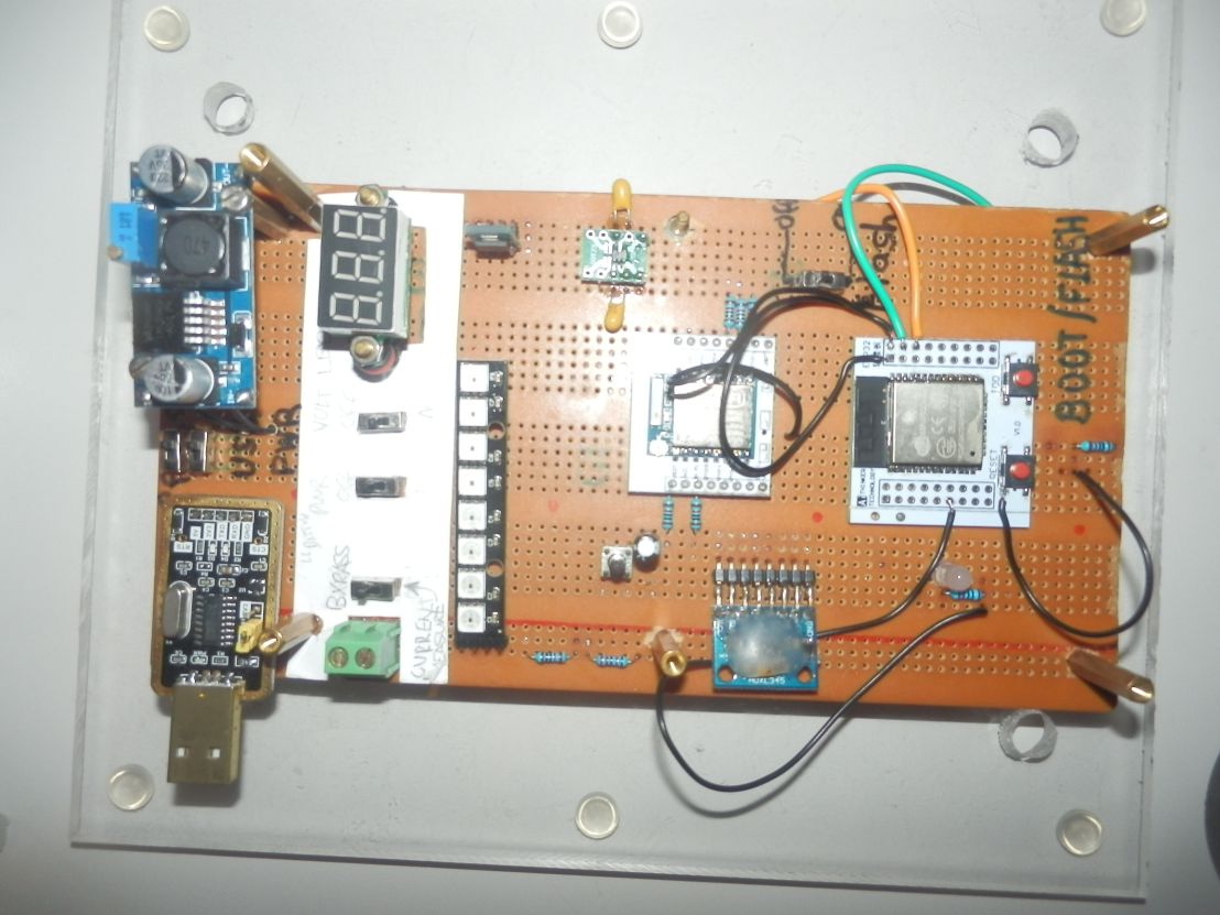
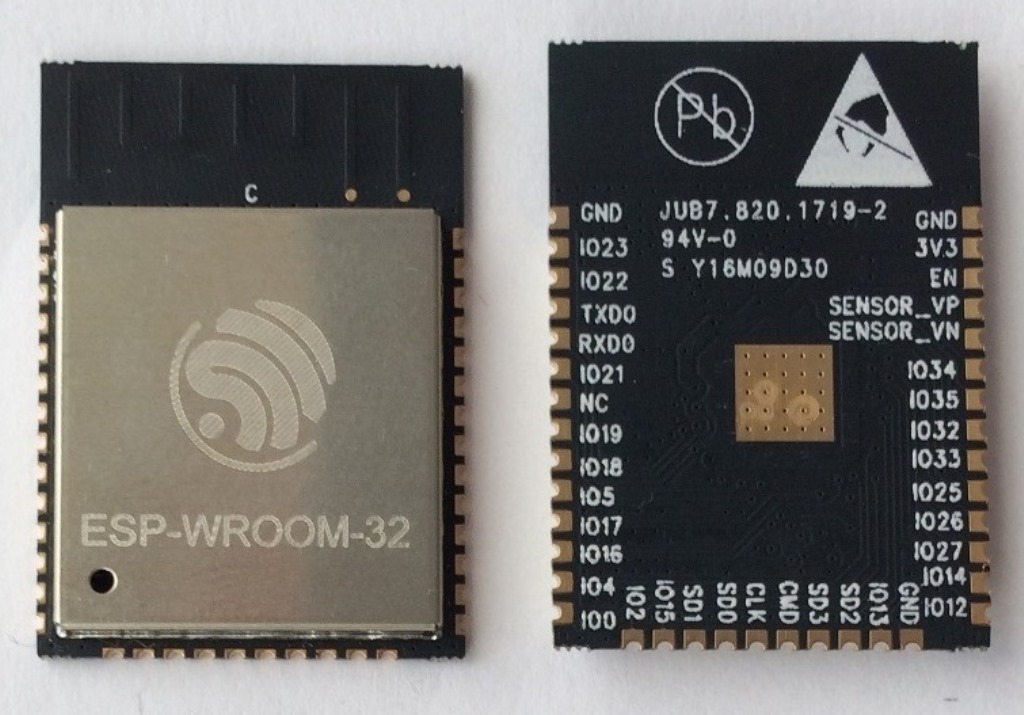
This image shows a hand wired prototype that is used to confirm all electronic components. Of most interest is the right hand side white square with the two red push buttons. On this white square the WiFi radio module (with dual core CPU) can be seen within the right hand side white area. It is the metal covered square with the tall black square on it’s left.  Actual size 1 inch wide.

In the centre of this photo is another smaller white square with a single core, slower less powerful WiFi module. This is not being used, since the more powerful dual core module is now working.

The other component of note is the new upgraded power regulator, also wired up and working to power the circuit. This can be seen on the small green square board with the two tan circular ‘lentil’ looking components towards the top row of the photo. The actual power regulator is the tiny small black rectangle in the middle of the green square.

The remaining components have all been wired up and used successfully on the previous V1 Talisman. The next task is to programming the new WiFi radio module with the dual core CPUs to communicate to the previously used components. (vibration motor, accelerometer, LEDs, battery charger.)  Once this component confirmation is completed, the components can be arranged to fit on a printed circuit board with their tested wiring.


Cascadia Retreat Beta Trial – Gnatt Chart

Following on from a great zoom conf call with Jean, Carolyn, Nader, Greg and Allan the following important dates for getting a beta trial prepared prior to the Cascadia retreat were entered into a Gnatt chart.


TalismanV2 Proj Plan

The key dates are:

14 March – Release of the Content Curriculum Course editor site.

26 March – Ship single functional (no apps) prototype V2 to Barre.

23 April – Release Portal for testing and bug detection.

30 April – Ship 9 Beta Talisman to Cascadia.

Exciting and busy few months!


More (Smart) LEDs

The Talisman V2 is using the CPU already included in the WiFi radio.  This Wifi CPU has less control wires made available than what was available from the independent CPU controller in Talisman V1.

In Talisman V1 there were 3 full color LEDs. Each full color LED used 3 wires – one wire for each of the red, green and blue LEDs. Therefore the Talisman V1 had used 9 control wires. (3 sets of 3 wires.)

Smart LEDs are being used in Talisman V2 to reduce the number of control wires. A large number of smart LED can all be controlled from one single control wire.

(This is achieved by sending the necessary color data for all the RGB LEDs over the single wire into the first LED. The first led then daisy chains the data passed along to the next LED in the sequence.)

The image above shows a V1 Talisman LED that with 3 wires on the left. On the right animated image is single smart LED. It can be seen in the right hand side photo that the little 5mm square LED has a dark chip rectangle and tiny gold wires within the white package. Each smart LED in V2 comes with a little chip inbuilt!

So, this posts shares how it is possible to reduce the number of data control wire by the use of smart LEDs from 9 to 1.  In addition it is possible to daisy chain a very large number of smart LEDs in a long sequence.

It is intended to add additional full color LEDs onto the Talisman V2, most likely in a circular ring or oval layout. This should allow the Talisman V2 to be orientated anyway an artists chooses. The Talisman V1 only had LEDs on the front edge, so V1 had to be orientated a certain way when artistically mounting.

Prototyping the smartLEDs today, uncovered a downside; they use power even when no light is being emitted! In fact their little internal chip uses so much power even when dark that they would over time significantly reduce the battery life.   For this reason it is necessary for the Talisman V2 to switch power off for the LEDs unless they are going to be shining.

It so happens that there is already a spare switched power available on the Talisman V2. The Talisman V1 used to have a Bluetooth controller that had it’s power turned on and off. This bluetooth is no longer required, so the second switched power is now used for powering on and off all the smart LEDs on V2.